Spindle Replacement
Though your Carvey’s spindle is quite durable, it may occasionally require replacement as all wear parts eventually do. It is important that your Carvey’s spindle only be replaced with a genuine spindle designed for Carvey. These are available for sale on our website. Please get in touch with our support team if you have any further questions about the instructions below.
Tools required:
- 2.5mm & 3mm Hex Keys
- Small Flat-Blade Screwdriver
- Blue Thread Locker
Estimated time: 15-30min
Step 1: Prepare
Shut down any active connection with Easel and unplug the USB cable from your computer and the Carvey. Power down the Carvey and unplug the AC power cable from the wall. Open the door and remove any material and clamps present. Remove the collet and collet nut as well as any milling bit that may be present. Clean any excess dust from the inside of the Carvey with a vacuum and soft brush if necessary (see cleaning instructions .) Since you will be working with small parts that are easily lost, it’s a good idea to have a small bowl or other container for bolts at your workstation.
Step 2: Remove Lighting PCB
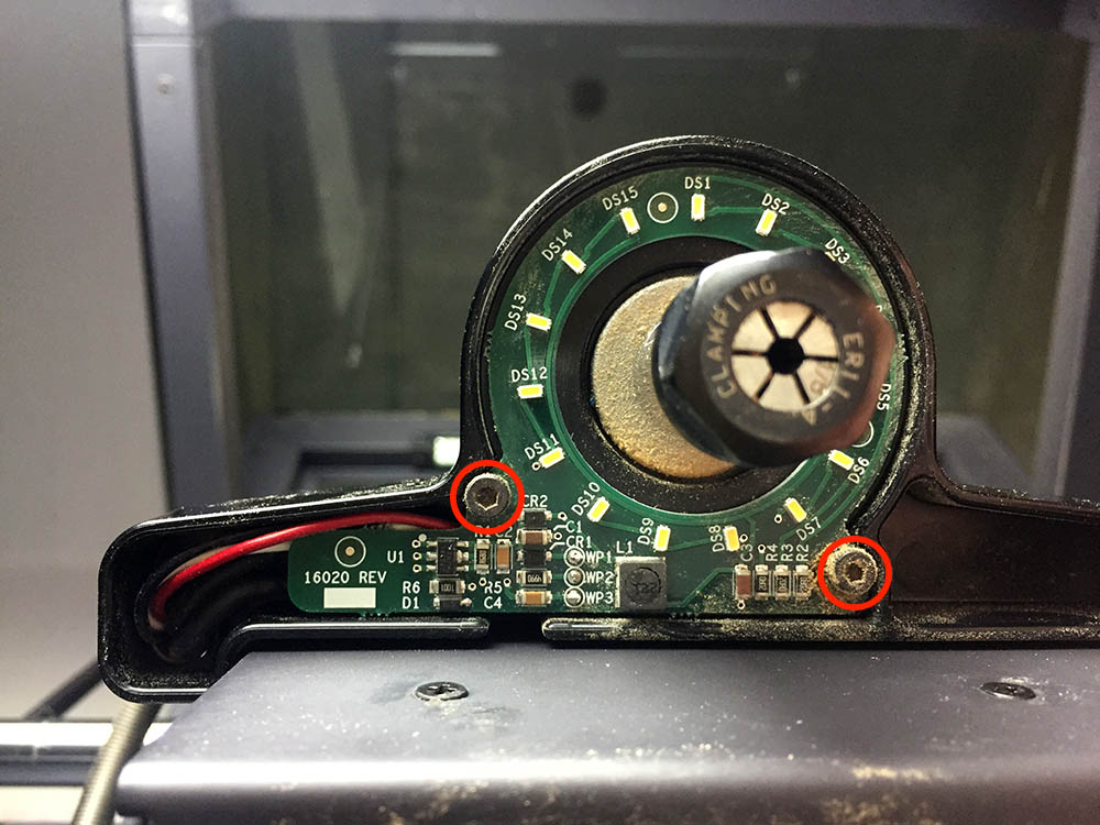
On the underside of the motor there are two small metric cap-head bolts that secure the lighting PCB and plastic bezel to the spindle mount. Loosen these bolts and set them aside. Gently lower the lighting PCB and remove it from around the spindle.
Step 3: Disconnect Spindle Wiring
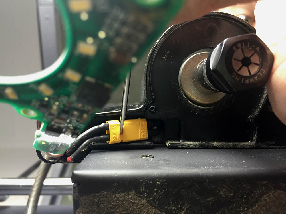
The spindle is connected to its DC power source by the pair of small yellow connectors that rest inside of the spindle bezel. Separate these connectors and remove the plastic spindle bezel, making sure that the wires are clear of the holes in the bezel. You may want to use a small flat-blade screwdriver to assist in prying the connectors apart. Note that one side of each connector has beveled corners that match when in the correct configuration. The connectors will not be able to plug into one another if any one is flipped.
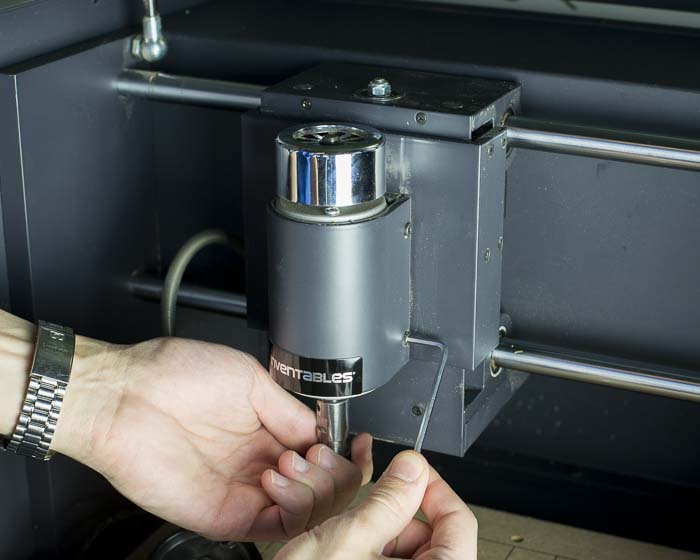
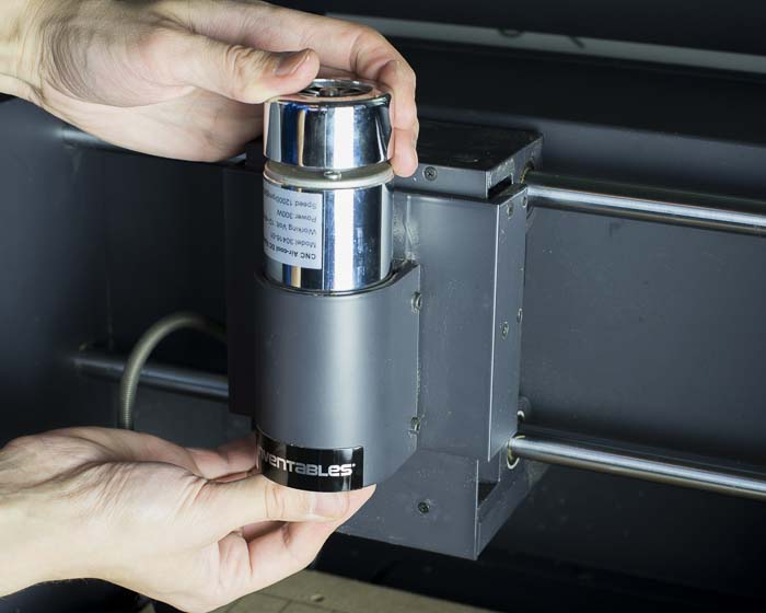
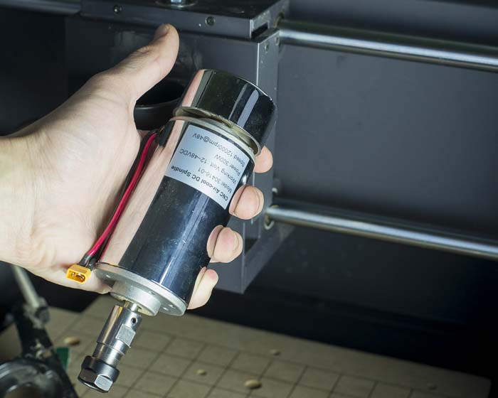
Step 4: Remove Spindle From Mount
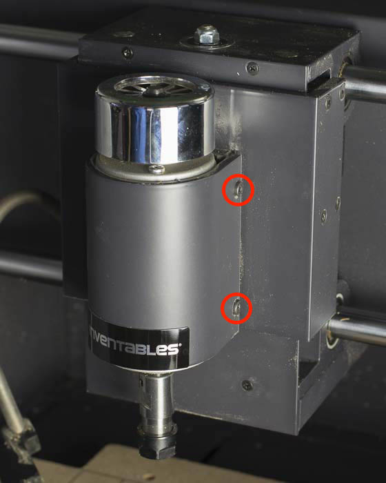
First, loosen the two 3mm bolts located on the right side of the spindle mount. Be sure to hold the spindle while loosening the mount to prevent it from slipping out accidentally. Once the spindle mount is loosened, push the spindle up through the mount, ensuring that the yellow power connector clears the slot toward the rear-left of the mount collar.
Step 5: Install New Spindle
With the old spindle removed, you can now prepare your new spindle for installation. Position the spindle over the mount and align the wires and connector to the slot in the rear-left of the spindle mount collar. Gently lower the spindle into the collar keeping the wires and their strain relief gasket in line with the slot. Align the bottom of the motor body with the bottom of the mount then tighten the two bolts on the side of the mount with a 3mm hex wrench.
Step 6: Replace Spindle Bezel and Connect Spindle Power
Raise the spindle bezel back to its original position, threading the yellow spindle power connectors through the holes in the bezel. Reconnect the yellow power connectors and make sure that they are properly seated in the bezel recess. You may initially need to push the cable guide on the left side of the bezel just a bit through its hole to make the connection.
Step 7: Fasten LED PCB and Bezel to Spindle Mount
Seat the LED circuit board in the bezel, taking care to ensure that the red white and black wires don’t get pinched between the bezel and PCB. Once the bezel is properly seated, apply a small bit of thread locker to each of the mounting bolts and insert them into their respective holes. Make sure that the bezel is properly aligned with the spindle mount then start threading the bolts. Tighten them with the 2.5mm hex key. The bolts ought to be snug, but not so tight that they cause damage to the PCB or bezel. If you have difficulty locating the threaded holes in the mount or getting the bolts started, remove the PCB and bezel assembly then thread the bolts into the mount by hand a few times, this will help clear out any residual thread locker that may be gumming things up. Once the PCB and bezel are installed, your new spindle is ready to carve!
Next Step: Belts