Machine Basics
Machine Diagrams
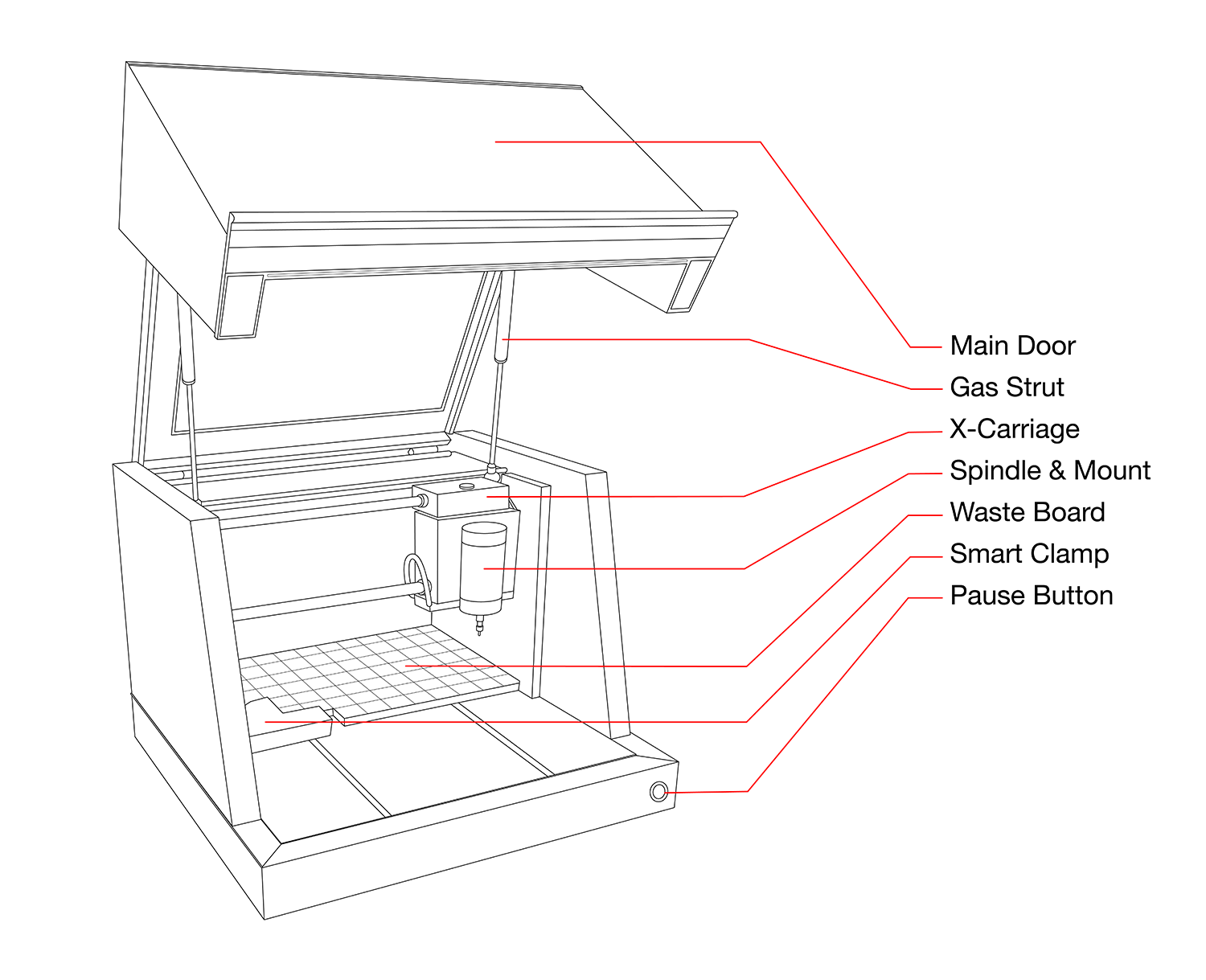
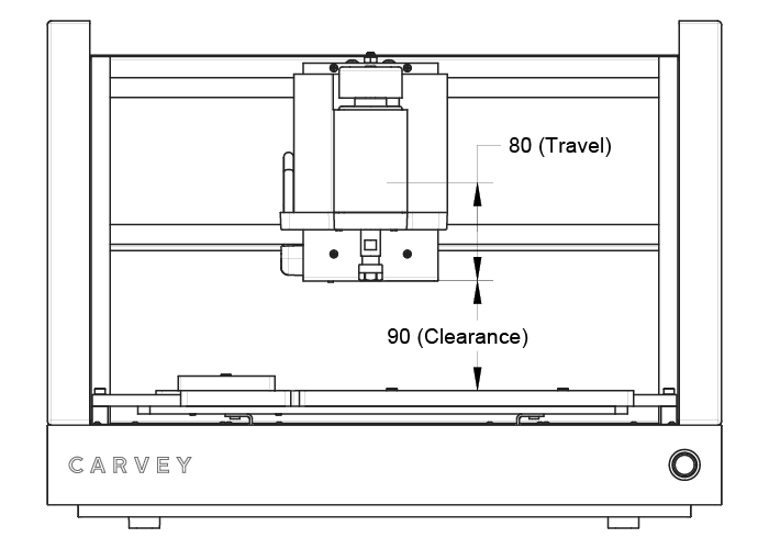
Machine Specifications
Your Carvey has a carving area of 11.6” x 8” (approximately 30cm x 20cm) in the X and Y axes respectively. Clearance in the Z axis varies depending on overall length of the installed milling bit, though the overall clearance from the waste board to the waste board to the cutting head is 90mm and the maximum travel of the Z axis is 80mm.
Changing The Bit and Collet
Changing milling bits on a Carvey is easy to do, though it requires some care to make sure that everything will work correctly. Unlike a drill chuck, the chuck on the Carvey is based on a collet system which holds the cutting tool more securely for lateral cutting work. Collets are interchangeable and have specific bore diameters that must be used with a tool that has an equivalent shank diameter and vice versa. Before changing out the cutting bit, make sure that your Carvey is powered off and unplugged. If you already have a milling bit installed, you must first remove it from the collet by loosening the collet nut on the spindle. Find the 13mm and 17mm wrenches in the tool kit that came with your Carvey and position them on the spindle flats and collet nut respectively. Turn the nut clockwise to loosen it and continue to loosen it by hand if necessary. You should now be able to pull the milling bit straight out of the collet. If you want to replace it with a milling bit of the same shank diameter, simply slide the new bit into the collet and re-tighten the collet nut to secure. The flutes of the cutting tool should not be touching any part of the collet bore as the pressure can damage the cutting surfaces and lead to tool failure. If you have a milling bit with a plastic collar, insert the bit until the collar hits the collet and tighten. Always make sure that your collet is free of debris and obstruction before inserting a new bit.
If you need to use a tool with a different shank diameter, say a 1/4” engraving bit, you will have to replace the collet as well as the cutting tool. To replace the collet, start by following the same procedure as above, but once the bit is removed, continue loosening the collet nut until it comes off of the spindle. The ER11-A collet is clipped into the nut with an eccentric retaining ring on the nut. To remove, use your thumb to apply sideways pressure at different points around the top of the collet until it tilts as far as it can in the nut. You should then be able to wiggle the collet free. To install the new collet, press it into the nut until it snaps into place. Confirm that the collet is properly seated and thread the assembly back onto the spindle. You can now install a cutting tool.
Carvey Toolchain Basics
Before we cover the basics of Easel, it’s useful to know what’s happening behind the scenes from a software standpoint. If you’re a seasoned pro at CNC you can probably safely skip this section. While similar in principal to many other digital fabrication tools like 3D printers or laser cutters, building something on the Carvey isn’t as simple as inserting a file into a program and telling the machine to print it. Before carving on a rotary CNC machine like the Carvey, one must consider the material to be cut, the type of milling bit doing the cutting, as well as how the material is being clamped to the work-holding surface; in this case the wasteboard that comes with your Carvey. When designing the basic model to be cut, and when creating the cutting paths themselves one must always keep in mind the eventual practical considerations that come with having a physical carving system with a moving cutting head.
Design
Much like technical drawing, a digital design is a pattern that gives lengths, widths, and other dimensions of a part to be produced. In the context of 3D carving, this can take the form of a 2-dimensional vector file or a 3D solid mesh file. Much like a technical drawing, a digital design file contains very little information on how the actual part is going to be produced by a machine. This allows a single design to be manufactured in any number of ways depending on the bit, material, etc. for 2D work we generally recommend starting with a program like Inkscape or Adobe Illustrator as they allow for effective manipulation of complex vectors. Easel has some limited vector editing capabilities as well as some very useful apps for creating boxes, gears, etc., but for general purpose work, a dedicated program is ideal. Designing and carving 3D objects is a more advanced topic which we’ll touch upon here only briefly. Generally any CAD program capable of exporting a .stl mesh file will work nicely for 3D design.
CAM/Toolpath Generation
Once the basic design has been worked out, we must use a program to determine how the design will be interpreted as cutting path. To do this we must know what sort of bit we will be cutting with as well as the proper feed rates and cutting depths that are appropriate to both the material being cut and the bit doing the cutting. These values can be entered in Easel or any other compatible CAM software that you may be using. Easel makes the process of selecting feed rate and pass depth relatively simple with its suggested values for various materials. These values tend toward the conservative side, though sometimes you may need to alter them either to get a faster cut or to slow down the feed for a small bit. Once parameters have been entered, the tool-paths themselves can be generated. These toolpaths take the form of gcode, which is a set of instructions telling the machine where and how to move. In Easel you won’t see this code since it automatically generates and sends it from within the program, though you can export your toolpaths as text gcode files from ‘Machine->Advanced’ in Easel. If you’re using another CAM package like VCarve or MeshCAM, you will have to export a gcode file using the proper Carvey postprocessor and import it with Easel. This ensures that the tool-paths will be compatible with your Carvey.
Sending the Code
Once toolpaths have been generated, they must then be sent to the Machine itself. The Carvey does this through a serial connection that sends gcode commands one line at a time to the Carvey. If the command has been sent to control the machine in inches, a command like
G1 X0.0500 Y1.5000 Z2.0000
will send the machine to the point [0.0500”, 1.5000”, 2.000”] in the Carvey’s coordinate system at the feed rate specified from wherever the machine was before. Once the movement is complete, Carvey will accept the next command for movement. G0 and G1 are the most common commands as they represent jogging and cutting motion respectively. If you are interested in what, exactly, the gcode commands mean, this is excellent resource which goes into great detail on this topic. A given gcode file may contain anywhere from around 20 instruction lines for simple files to 100,000+ for more complex toolpaths.
Next Step: Working with Materials