Tensioning and Replacing Belts
Your Carvey’s X and Y axes are controlled by stepper motors attached to large reinforced GT2 belt loops. Though it’s unlikely that you will need to replace these belts until many years of use, they will stretch over time and occasionally break. The following instructions will take you through the process of accessing the belts for adjustment or replacement. This process can be somewhat tricky, particularly if you’re replacing belts, so it is important that you read the instructions thoroughly before picking up any tools.
Y Axis Adjustment/Replacement
Tools Required:
- 3mm Hex Key
- 2.5mm Hex Key
- 2mm Hex Key
- #1 Philips Head screwdriver
- #2 Philips Head screwdriver
- Blue Thread Locker
Time required: 30min
NOTE: if you are just tensioning your Y axis belt, you can skip to step 4. The center floor plate can slide out from underneath the carriage similar to the cleaning process. You can find more on this here .
Step 1: Prepare
Before working on your Carvey, you should disconnect any USB connections, power down your machine, and unplug it from AC power. Remove any materials and clamps that may be attached to the board. Use a vacuum to clean the inside of the machine of any dust or swarf that’s present in the machine. This will help prevent particulate contamination in the electronics below the board. You should have a small bowl or other container at your workstation for small bolts and screws that are lost easily.
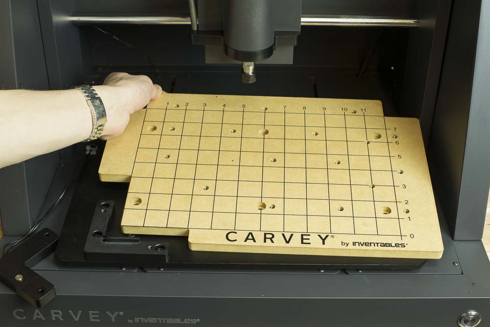
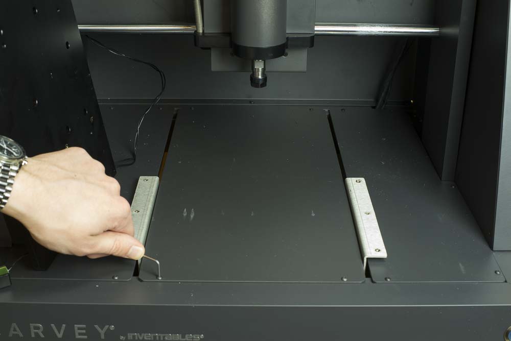
Step 2: Remove Waste Board
Remove the two bolts on the smart clamp and set the L shaped clamp to the side. Use a 3mm hex key to remove the six mounting bolts from the waste board and remove the board from the carving bed. For more details on this process, take a look at our article on replacing your waste board.
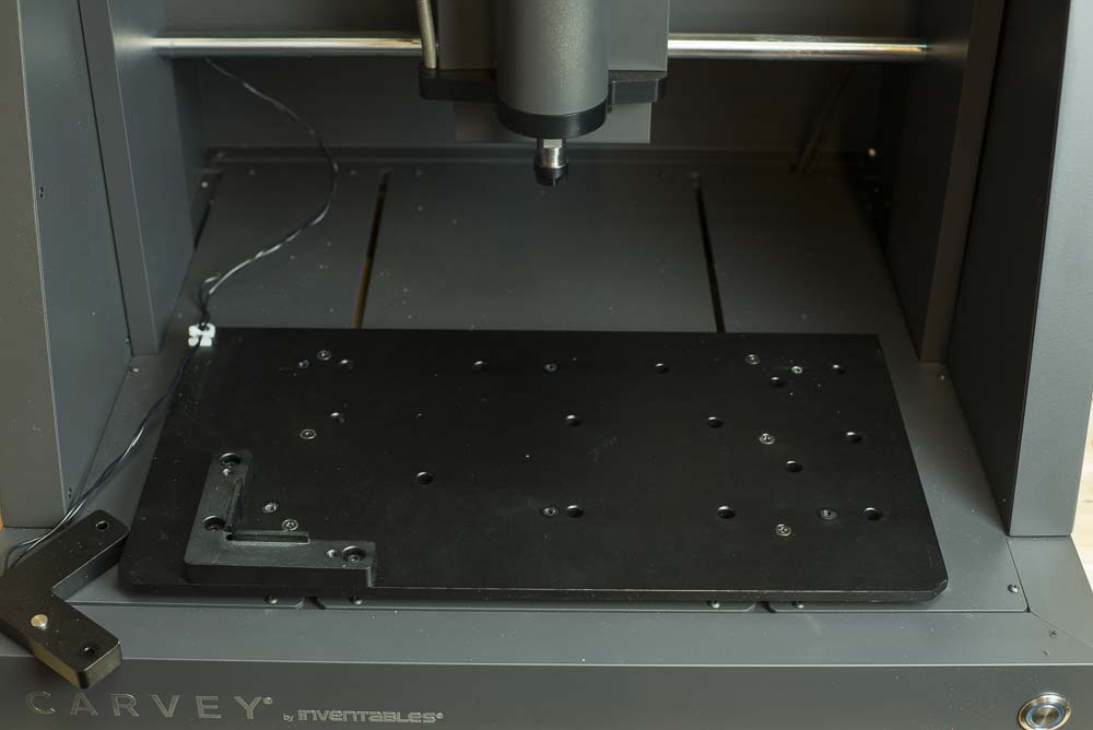
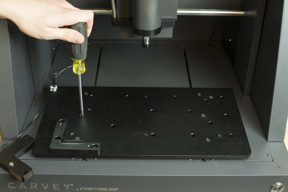
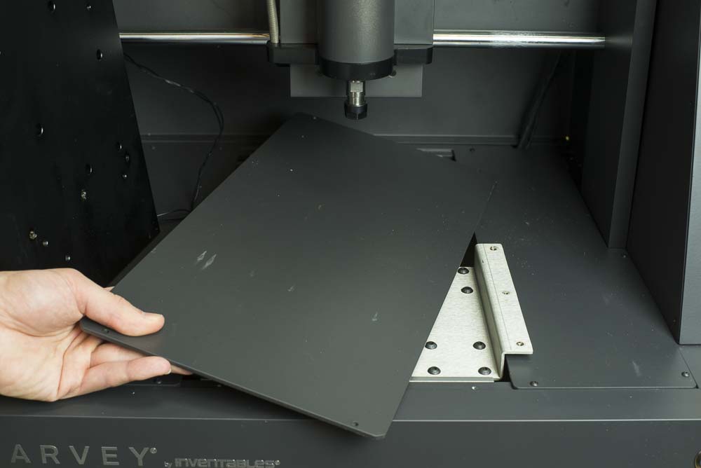
Step 3: Remove the Carving Bed
Once the waste board is removed, you can remove the metal plate that it bolts to using a #2 Philips head screwdriver. It is important that you use a #2 screwdriver that is in good condition and without excessive wear to the tip to avoid damaging the screw head. You may have to apply some pressure at first to prevent the screwdriver from camming out of the screw head, but once the thread locker has been broken, you should be able thread the screw out without too much trouble. Set the screws aside.
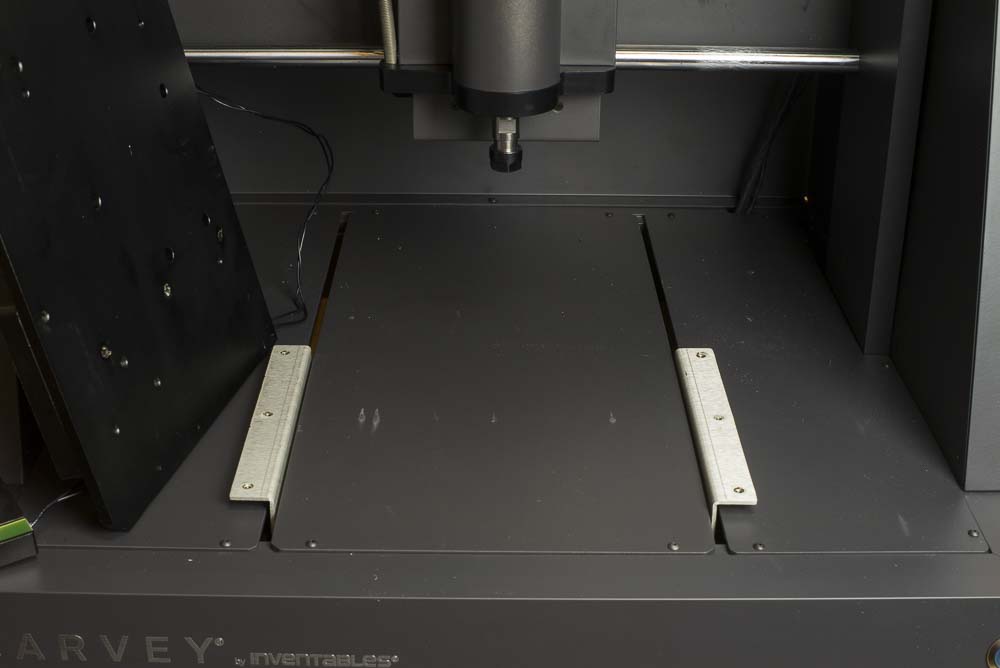
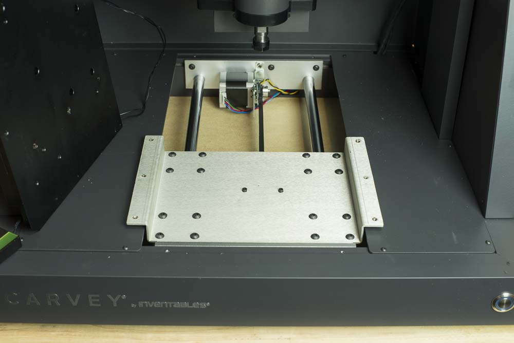
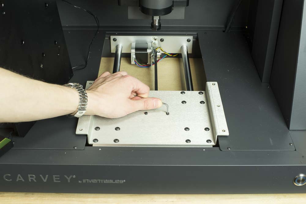
Step 4: Remove the Central Skid Plate
Locate the four small bolts located near the corners of the central skid plate. Use a 2mm hex key to loosen and remove the bolts then pull the plate off of the frame. This will expose the Y axis carriage.
 NOTE: At this point you will be able to tighten the belt with the front idler bracket if the belt has stretched. If you are tensioning the belt, follow step 4a. If you are replacing your belt entirely, skip to step 5 and continue from there.
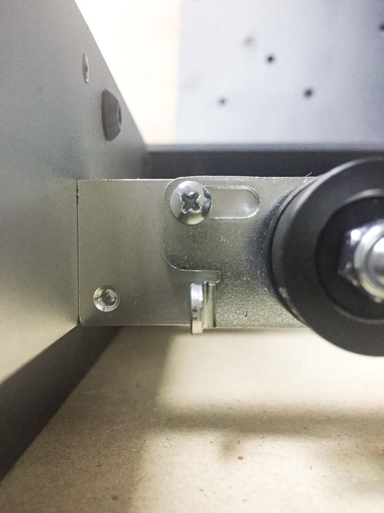
Step 4a: Belt Tensioning
Over time, your belt Carvey’s belt will stretch and may require tightening to prevent a loss in cutting accuracy and performance. At the front of the belt loop is a tensioning idler that is mounted to a bracket. This bracket has horizontal mounting slots which allow it to be adjusted back and forth. Use a #1 philips head screwdriver to loosen the bracket and move it back until the desired tension is reached. The bottom of the belt ought to emit a low audible note when plucked. Once you have properly tensioned the belt, tighten the screws on the idler bracket.
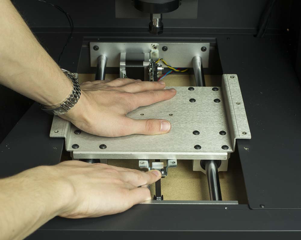
Step 5: Disconnect the Belt Bracket From the Y-Axis Carriage
The closed loop belt that moves the Y axis is connected to the main carriage by a small metal bracket. To access this bracket it must be freed from the carriage. Locate the two small socket head cap screws at the center of the carriage. Use a 2.5mm hex key to remove these screws.
 Slide the carriage backwards and pull the top of the belt loop towards you. The bracket will catch on the front lip of the carriage, so you will have to press the belt down a bit so it can clear the carriage.
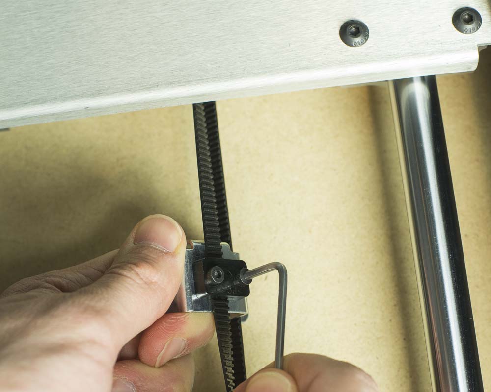
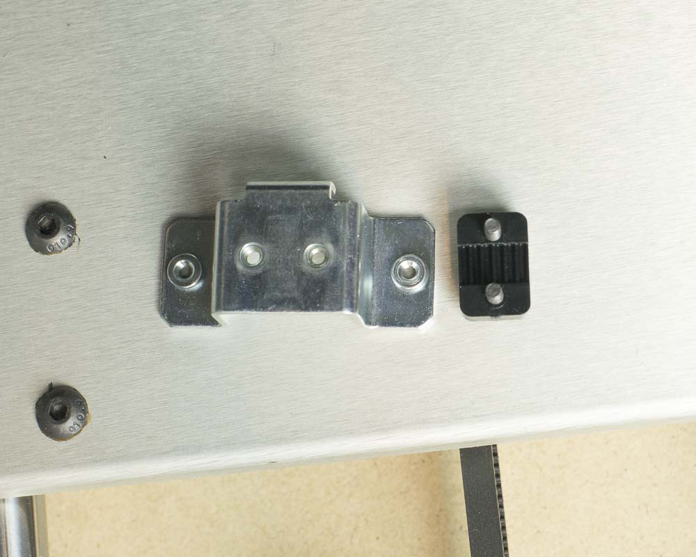
Step 6: Remove the Bracket From The Belt
In theory, one could also remove the bracket once the belt has been removed from the idler and pulley though we’ll present this step first for the sake of simplicity. Twist the bracket to access the socket head bolts on the bottom and use a 2.5mm hex key to loosen the clamp. Note that the plastic clamp has a row of teeth down its center that engages the GT2 belting and ensures a solid connection to the bracket. Keep this in mind when reseating a new belt in the bracket.
Step 7: Remove the Belt
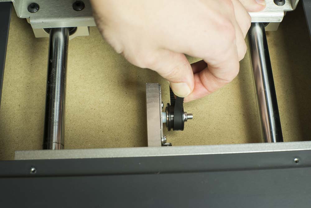
If your belt has broken, the hard part of this step has likely been taken care of for you, though if the belt is still intact you will need to first work the belt off of the idler by lifting the belt over the outer flange of the idler. If necessary you can loosen the idler bracket, though this shouldn’t be necessary. Once the belt is off, you can disengage the other end from the stepper motor pulley at the back.
Step 8: Replace the Belt
This is effectively the last step in reverse. Loop the belt around the stepper motor pulley, making sure that it is between the two flanges. Feed the other end of the loop underneath the Y axis carriage and gingerly coax the belt onto the idler over the outer flange. If necessary, adjust the tension on the belt with the idler bracket. Reattach the mounting bracket to the belt and slide the bracket back underneath the main carriage. Line up the holes of the bracket with the holes in the carraige and thread the two screws into the bracket. You may need to stabilize the bracket from the bottom with your hand to get the bolts started. You can now follow the disassembly steps in reverse to reassemble your machine. Make sure to apply a bit of thread locker where needed.